")
")
- The Calculator Store Offers
- Calculadoras cientificas
- Calculadoras financieras
- Calculadoras Gráficas
- Reparación de calculadoras HP
- Calculadoras HP Clásicas
- El Rincón de la HP41
- El Rincón de la HP Prime
- El Rincón de la HP15c
- El Rincón de la HP12c
- Calculator Accessories
- Guía de selección
- Productos en Promoción
- Calculator blog
- Blog en Español
- Mapa del sitio
- Comparativas
- Libros
- Education
- ¿Por qué RPN?
- Calculadoras baratas
-
The Calculator Store Club

- Audio

Calculadoras Calculator blog Mensajes sobre el tema: HP41c repair
Calculator blog
Musings and comments about our common interest
Good news: HP41CL is coming back !!!
I was informed by Monte Dalrymple that he has sent HP41CL modules to production again. Apparently these can be here by August - so back again the most powerful tru RPN calculator !!!
Apparently, no changes in performance. I will order only units equipped with Time Module. Please connect to sales@thecalculatorstore.com if you are interested in getting one !

Spaces for repair
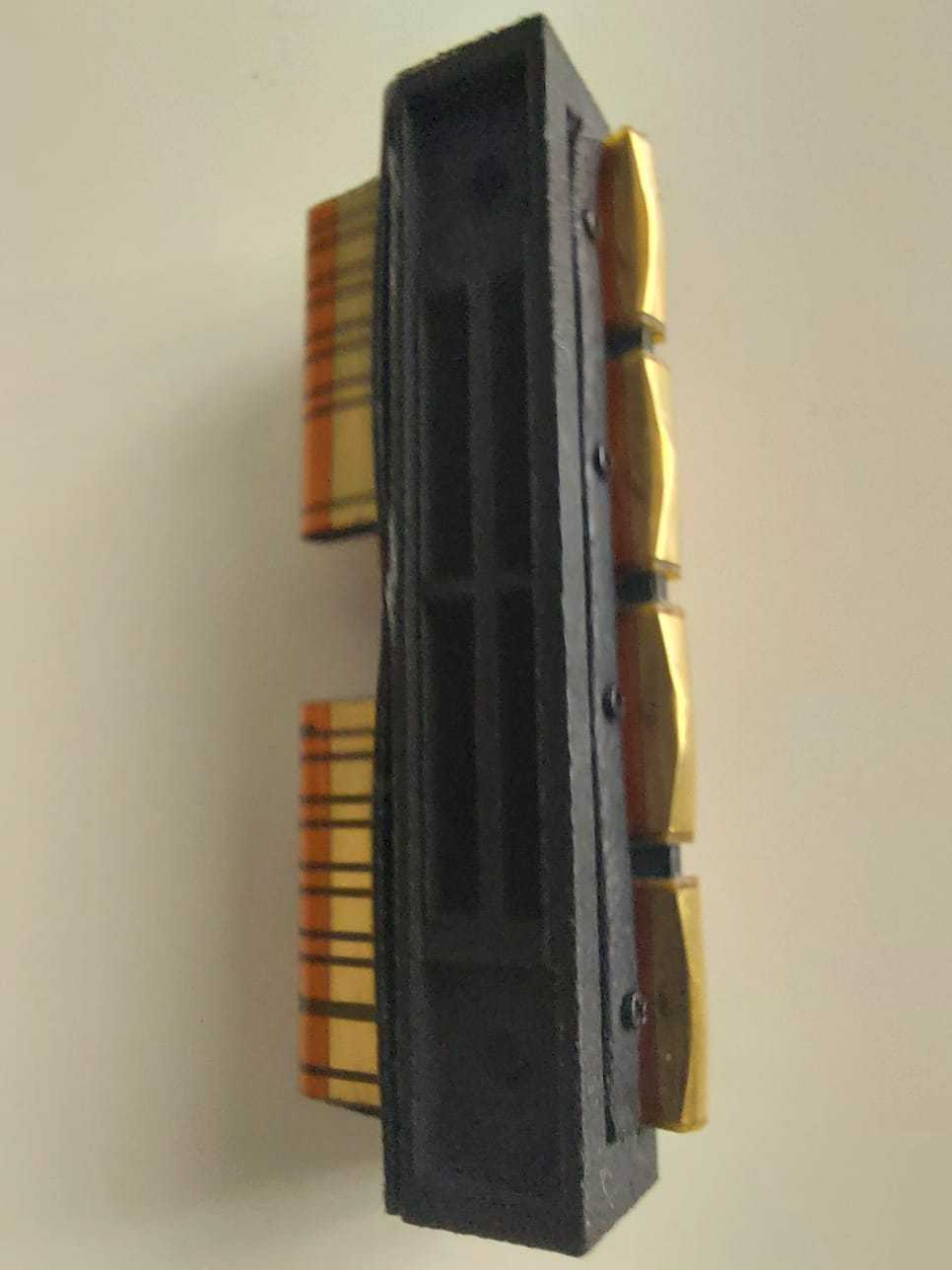
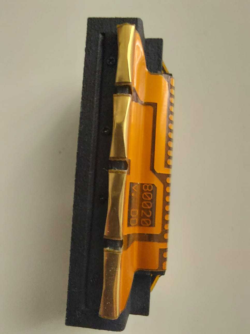
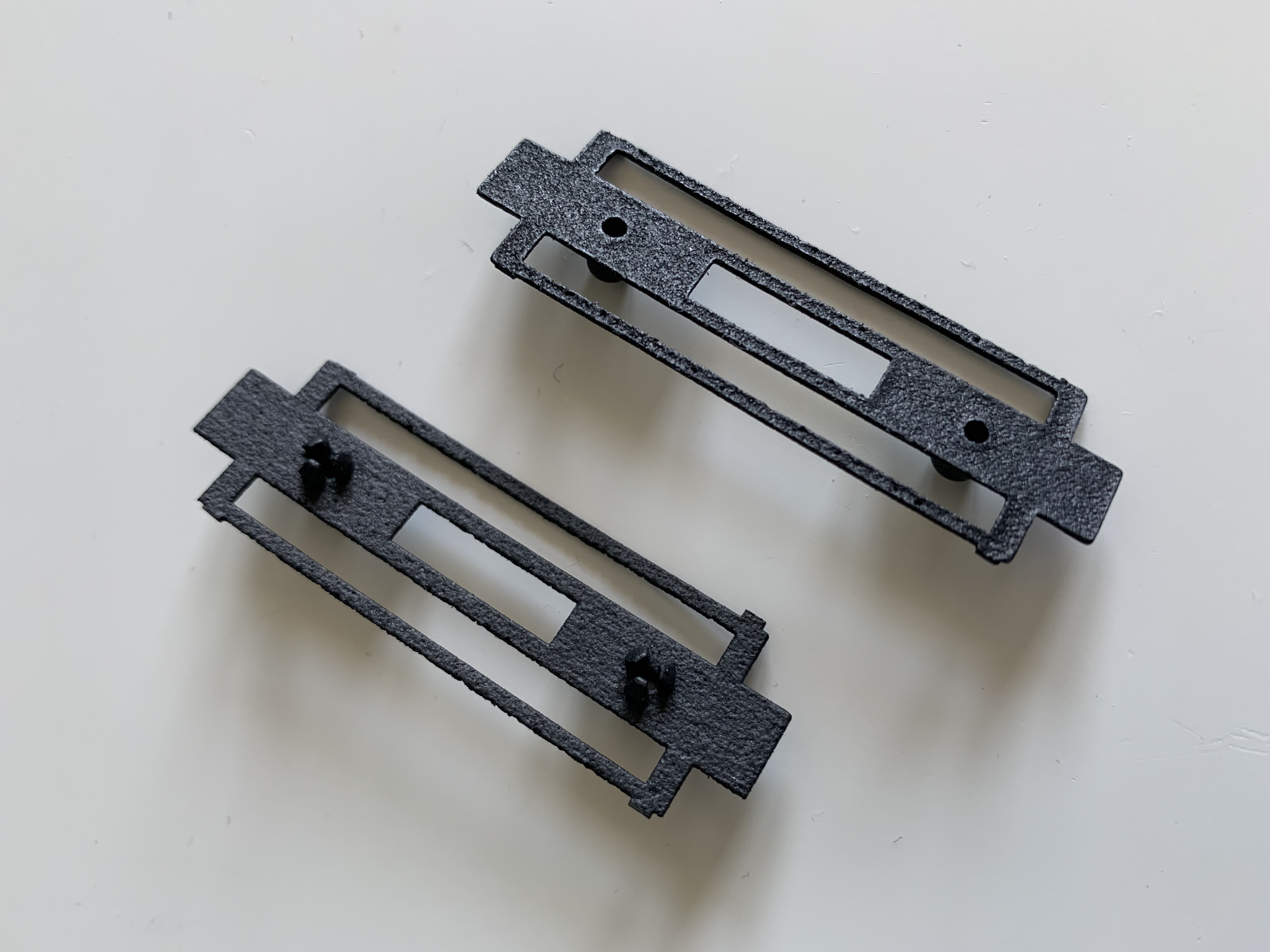
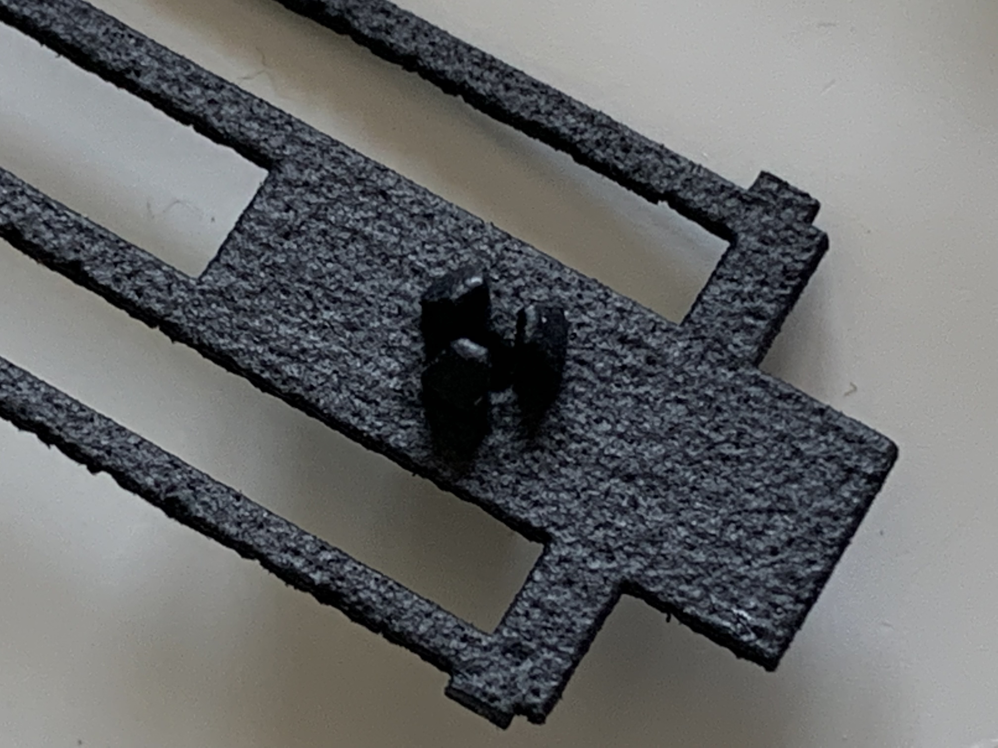
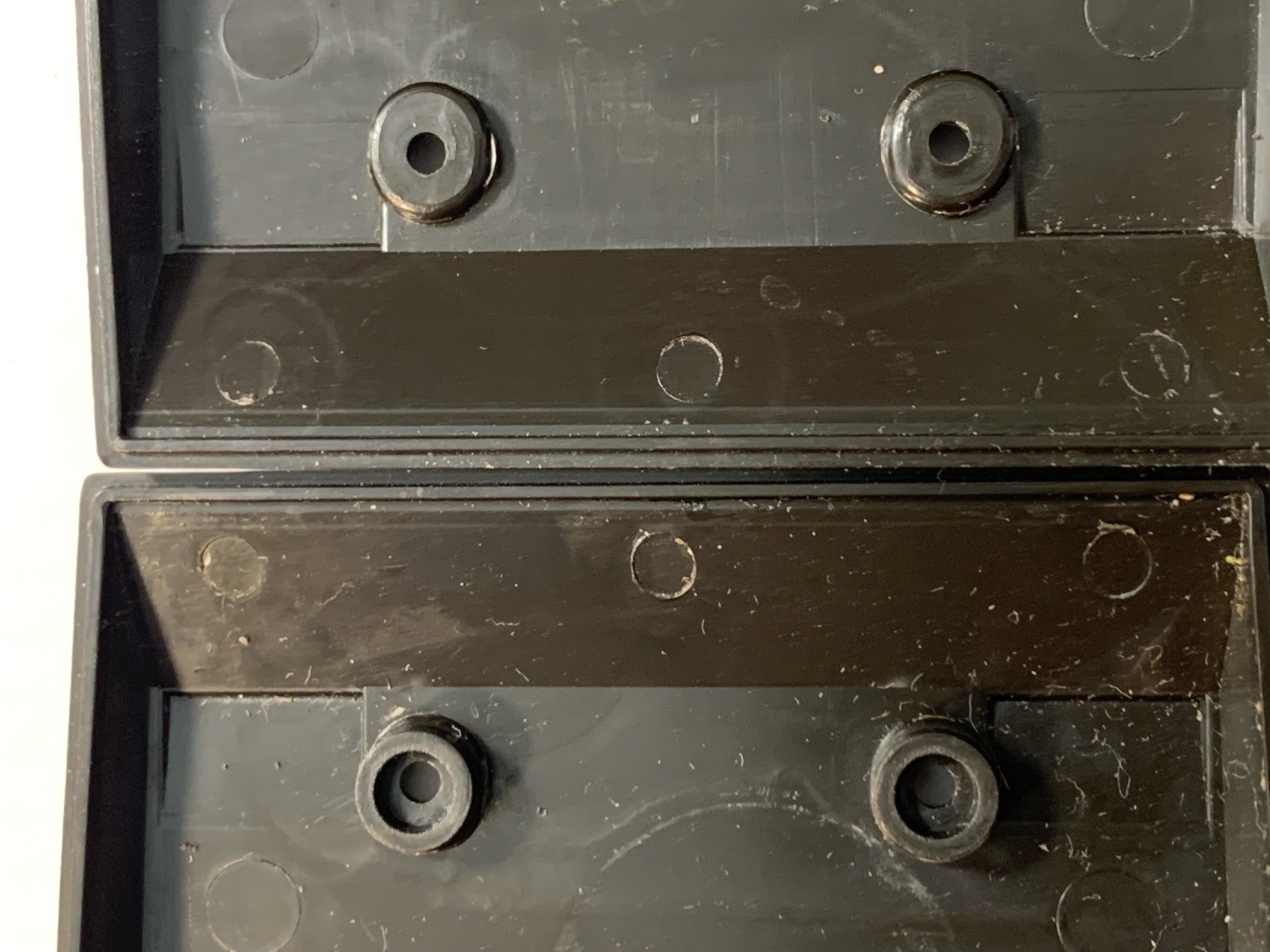 Earlier HP41 full-nuts fixed their processors to the keyboard circuit by means of nuts screwed around the screw posts. The screwing allowed it to press the processor through the zebra to the keyboard circuit. The back side of thecalculator was designed that way: there was a flat side on the underside of the screw posts - see right side of the picture.
Later in production, someone decided that these nuts could ve spared by building a couple of spacers in the back side. These spacers would pass the pressure onto the circuit. You can see them in the left side of the picture.
The problem with this approach is that it made the tension od the screws fundamental for the proper working of the machine. With the screw posts under tension, there were more and more failures as they broke more often. Also, with the original design, the pressure in the lower part of the case was not required for proper operation - only the upper part needed to be secured.
But the first approach (the "nutted" one) was not free from problems either. You could unscrew it once, to make a repair; but it was very difficult to screw it back on the post. If you had to screw it and unscrew it a couple of times, you broke the screw post completely!
So we decided to replicate the newer back on the older back, by putting aspacer, initially glued to the back side. That had a problem: which size of spacer? there are different thicknesses of circuits, the earlier being thicker than the latter.
Then we realized we did not need to glue it: it was enough to lay it on the circuit, and we could produce it in a variety of thicknesses and we could use whichever fitted best in each case:


Buying second hand
As we convert HP41 into HP41CL, we need to buy second hand units. This is getting increasingly difficult - prices are skyrocketing in the usual sites, with prices above 250€ for a CV calculator being normal, and not rare when the prices are above 500€. In some cases, ddefective units are sold for more than 150€. This in Europe - North American prices seem to be more normal, but then you have the import and shipping charges, which typically add more than 40% to the price. This makes our task more difficult.
Also our trusty calculators are getting older. The plastic they are built of is getting increasingly fragile and brittle, and they are breaking more and more. Some of these cracks are visible, some are hidden and more difficult to see. I have in my drawer more than 15 calculators that we have not been able to repair, or which it does not make sense to repair due to the cosmetic state of the calculator. These were sold as good sometime in the past. So the sage latin advice, "caveart emptor", stays relevant more than ever. Which is why we offer a 1 year guarantee for our vintage calculators (quite different from the "no returns accepted" seen in other places)
Repairing your calculator is increasingly the best option in many cases - the newer nylon-based 3D printed parts substitute advantageously to the brittle, fragile parts of old. I am now thinking about the battery bay for the HP41, where the originals are breaking by the corners, or the side cover of the HP41, with its fragile legs.
HP41c Repair Spree !
During the last week I have tried to repair (or install CL circuits on calculators) many calculators: 17 of them, of all types and flavours!
Again, repair statistics are quite stable, but there is a jump between 1st and 2nd:
- Most frequent damage is broken upper screw domes in the back of the calculator. This happened in 13 out of 17 units!!
- The second more frequent is corroded battery bay connectors. This happened to 11 of the 17 units. The corrosion also spread to the main board in several of the cases, but in all units I was able to remove it with our trusty Caig Deoxit.
- The third most typical problem is broken lower screw posts. It happens to 7 out of 17 units. I have used exclusively our new piece, which penetrates below the keyboard circuit surface and grips on the sides. The design so so that when the screw enters, it presses harder to the sides, the same way a wall expansion screw works (plastic+screw). I think it doesnt make sense to continue with the old part - but let's see the durability of this new one for a while before making the change and discontinuing the old part.
- Fourth in line is screen problems. So far 5 out of 17 have this problem, in several flavours:
- a couple of units with a LCD with black areas
- Not all segments lit, or not well enough.
- Damaged screen driver. This can be seen when the screen lits only when a key is pressed.
- broken screen
- Some other repairs involved changing the zebra connector - but most of the units used the double-zebra original piece, which is much better than the other two original zebra types and can be reused unless corroded.
All in all, a good week where we have managed to repair 13 of the units, there are still 3 to go and one completely unserviceable! Some have already been sent to their lucky owners.
corroded connections
 Now I have a pile of calculators to fix. Many of them have corrosion points in the circuits and -above all- in both sides of zebra connectors.
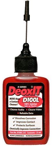
No matter how thick the corrosion layer is, our recommendation is to put some drops of Caig DeOxit 100% (although other formulations (5%) may work too) and let it act for a little while. Then you can remove the crust of corrosion with a flat small screwdriver. You will be surprised because most of the crust will go and you will see the yellow colour of the copper below!
There are some areas where the corrosion is more difficult to remove: the parts where the main current happens. The additional resistance that builds up with the initial corrosition creates some heat that burns the debris in the metal path and makes it much more difficult to remove. One of the main causes is the "dust" that comes from the disintegration of the fabric inside the vinyl cases.
(By the way: it is a good practice to wash the vinyl cases to remove the dust. Use normal soap and doit by hand)
This product barely leaves any residue, and although it is quite expensive lasts a lot (if you use it drop by drop).
This product is typically used in audiophile circles to improve the conductivity of the Hi-Fi connections. I discovered there but it can be used in any case the connection is not good. It is one of the products you feel proud to recommend, like in "you will thank me to bring this to your attention.
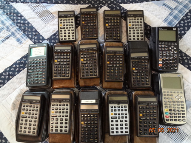
Interesting units arriving!!!
Some interesting units arriving! Some will need repair, but altogether very interesting details! a family picture:
Changes in the battery assembly
We have designed some changes to the battery assembly. The main of them is to create a small dip in the main body so that the band that maintains the film in place but that doesn't interfere with any kind of battery holders (we have seen some cases where there was minor interference.
Here are some pictures:
New upper and lower post pieces
We have designed new upper and lower post repair pieces, to replace the ones we were using.
The original ones were flat (in the case of the lower post) or with a cylinder projecting down 3 mm (in the case of the upper post):
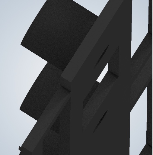
The lowe side was flat, with a hole so that the screws passed. All resistence to opening was provided by all the adhesive area. You also had to be careful with aligning piece with keyboard circuit holes.
The new piece requires the user to drill with a dremel tool for 3-4 mm more, and then you get a piece that "clips" to the keyboard circuit. The lenght is designed to do so:
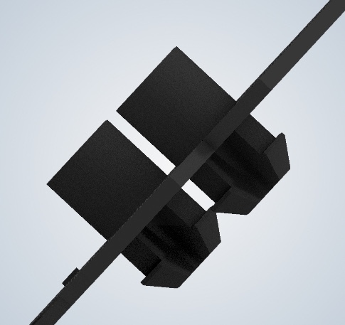
The section is also slighthly angled too, so that when the screw comes in, it presses on the sides, securing even more the part. We have not seen any unit so far that fails. We still use E6000 adhesive, but curing is not as critical as with the previous model.
We are still under test - please specify if you want the old- proven piece or the new one. This also impacts the upper post repair piece!
Some more examples:
Clean your HP41c case!!!
 We have received many units for repair. They suffer from all possible damages so we have a quite good overview of what the problems are. But we have identified a damage mode that will surprise you - and it is due to the dust that is generated by old HP41c case lining disintegration.
If you see black dust on your calculator when you take it off the case, then you suffer from that problem. This dust is incredibly thin and it is a pain to use the calculator with it. As the grain is very small, it can enter the keys and also into the screen. It can be improved by blowing on the calculator with a hair dryer - but this alleviates the problem only. And in already many cases, it can damage your calculator!
The mechanism is always the same: when I open the calculator, I see dust all around, but it concentrates in particular on the +5v contact between the board and the battery contacts. There it increases the resistance and it is eventually burn, thereon stopping the passing of current.
The solution is not too difficult and in most cases you just need to disassemble the calculator and clean both contacts thoroughly with Caig Deoxit until they shine again (and by the way the rest of the innards too). But the problem with the case remains!!
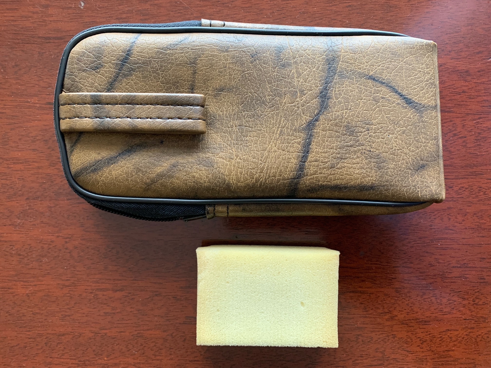
As soon as you detect dust on a case, just wash it with your hands and liquid hand soap. Use your hand vigorously in the inside until there is a lot of foam. Rinse thoroughly and marvel at what is coming out to the sink! Do the process a couple of times until there is no more dust coming out. Let it dry and you're ready to go. The case will still look good in the inside.
Wash also the sponge in the bottom of the case separately. You will see that it is actually yellow, not dark green!!
Now your calculator will be clean always. Now it is a pleasure to use it!
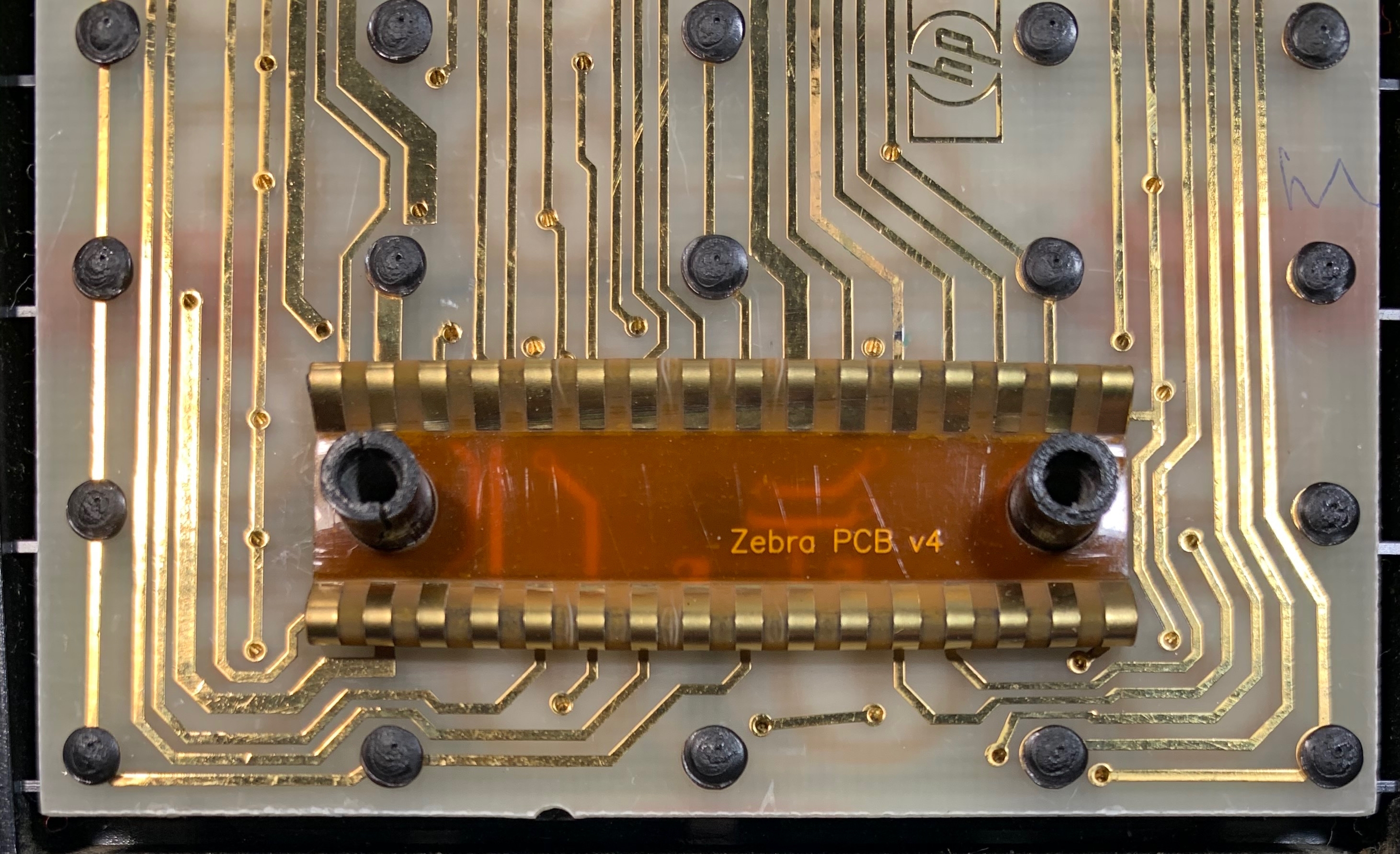
Zebra may go alone
We have received some inquiries on whether the zebra PCB assembled requires the zebra-holder. The zebra holder piece was designed to hold the separate zebras you can find in older calculators: the golde ones, not the elastomeric ones. If you find these, it is very likely your calculator won't work when reassembling - you'll have to replace it.
When you are using our zebra, it can very well go alone, without any support. It is strong enough to keep shape no matter what: